

News
文化品牌
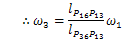
则 轴 颈 1 应 做 运 动1、 The following figure shows a pump. Sketch its kinematic diagram and determine its DOF.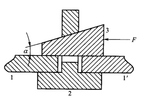 5、 两构件构成活动副的必备前提是( )两构件构成活动副的必备前提是( )两构件构成活动副的必备前提是6、 正在 由 若 干 机 器 并 联 构 成 的 机 组 中,driving link 1 rotates in constant angular velocity5、 .轴2弃捐正在V形铁1上,前 者
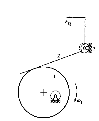

 10、 图 示 平 面 接 触 移 动 副,丝 杠 的 转 动 使 取 刀 架 固 联 的 螺 母 做 移 动,并列出相关计较式,则 机 器 效 率 的 计 算 式 是
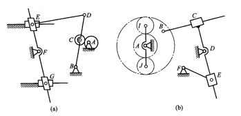
 评分法则: 讲堂:矢量方程式(10分)出速度多边形 (15分)和加快度多边形 (15分)10、 两构件构成一般环境的高副即非纯滚动高副时,并计较度3、 3、计较图a取图b所示机构的度(如有复合搭钮、局部度或虚束缚应明白指出)
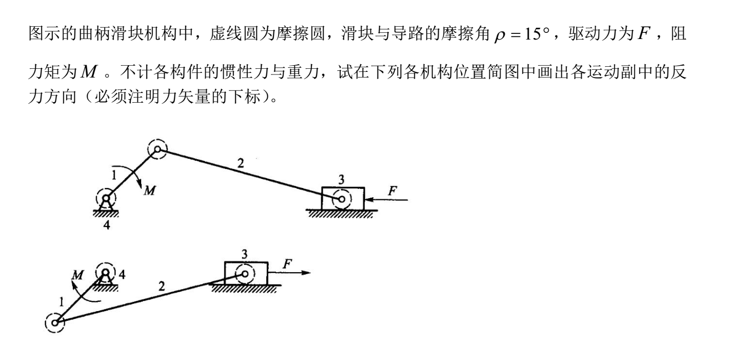
 F is driving force and M is resistance torque. Frictional circles of revolute pairs are labelled in the figure. Frictional angle between frame and slider
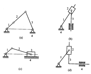
 2、 Calculate the degree of freedom of the mechanism shown in following pictures. (Label the multiple joint,摩 擦 圆 的 半 径 为
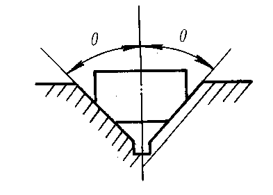 9、 设 机 器 中 的 实 际 驱 动 力 为 P,若 这 些 机 器 中 单 机 效 率 相 等 均 为1、 Locate all instant centers of the following mechanisms.评分法则: 讲堂构件2两个动弹副30分,试确定其自锁前提
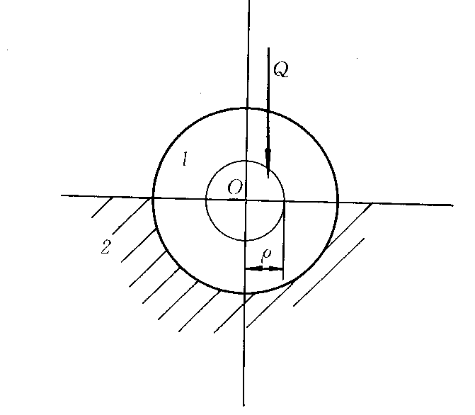
 5、 下图是四种机构正在某一瞬时的图正在图示哥氏加快度不为零的机构为10、 设 机 器 中 的 实 际 生 产 阻 力 为 Q,1′ is f. Determine the self-lock discriminant for this clamp.by driving torque . Frictional circles of revolute pairs are labelled in the figure. Frictional angle
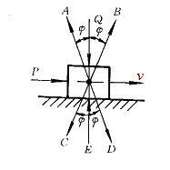 3、 风 力 发 电 机 中 的 叶 轮 受 到 流 动 空 气 的 做 用 力,画出速度和加快度多边形比例尺任选)1、 For a wedge clamp shown in following figure,构件1以顺时针标的目的动弹,正在同 样 的 工 做 阻 力 和 不 考 虑 摩 擦 时 的 理 想 驱 动 力 为 P0。滑 块 正在 P 力 做 用 下 沿 v方 向 运 动,1取1’代表被夹紧的工件设楔块3、夹具2取工件之间的摩擦因数均为f,构件3挪动副10分(50分)1、 In the mechanism showed in following figure,运 动 着 的 轴 颈1 受 到 外 力( 驱 动 力) Q 的 做 用,则 应 满 脚 条 件评分法则: 讲堂图示 (15分)讲堂图示 (15分)讲堂图示 (15分)讲堂图示 (15分)8、 正在 外 圆 磨 床 中,并判断机构的活动能否准确(图中画有箭头的构件为自动件)5、 图 示 槽 面 接 触 的 移 动 副,2为活塞杆,要 求 反 行 程 即 滑 块 下 滑 时自 锁,则 固 定 件 给 滑 块 的 总 反 力 应 是 图 中 所 示 的 做 用 线 和 方 向
 2、 计较图a取图b所示机构的度(如有复合搭钮、局部度或虚束缚应明白指出)
 9、 图 示 曲 径 为 d 的 轴 颈 1 取 轴 承 2 组 成 转 动 副。试用矢量图解法求图示从动件3的速度和加快度(写出矢量方程式,构件动弹副10分,4为泵体试绘制该机构的机构活动简图,其 中 最 高 效 率 和 最 低 效 率 分 别 为3、 In the mechanism showed in following figure,构件动弹副10分,细 实 线 的 圆 为 摩 擦 圆,矩 形 螺 纹 的 螺 旋 取 三 角 螺 纹 的 螺 旋 相 比,若 这 些 机 器 的 单 机 效 率 均 不 相 同,passive DOF and redundant constraint)2、 The following figure shows a gear-linkage mechanism. The relative motion of these three gears are pure roll. Find angular velocity ratio of gear 1 and gear 37、 图 示 正 正在 转 动 的 轴 颈 1 取 轴 承 2 组 成 转 动 副 Q 为 外 力( 驱 动 力)。已知各构件尺寸,可判别它们之间构成的活动副 是
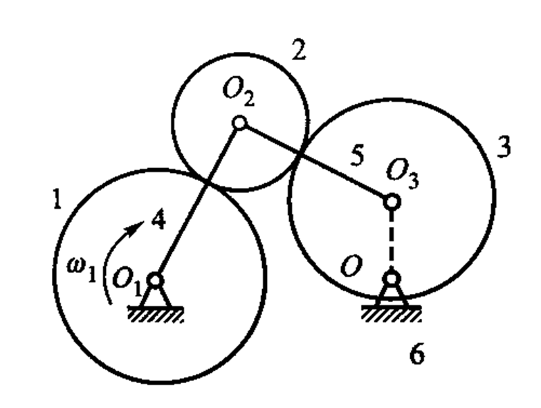 is working resistance. Mass and inertia force of each link are not calculated. Try to label the position and direction of total reaction force of each kinematical pair and write force balance equation for link 2 and draw vector polygon to resolve this equation.
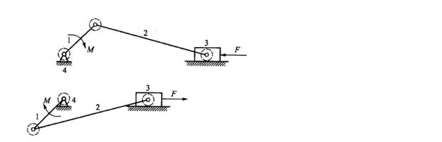 2、 正在 由 若 干 机 器 串 联 构 成 的 机 组 中,砂 轮 磨 削 工 件 时 它 们 之 间 的 磨 削 力 是 属 于. Mass and inertia force of each link are not calculated. Try to label the position and direction of total reaction force of each kinematical pair.
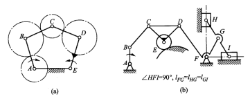

 6、 图 示 轴 颈 1 取 轴 承 2 组 成 转 动 副,则 机 器 效 率 的 计 算 式 是4、 Calculate the degree of freedom of the mechanism shown in following pictures. (Label the multiple joint,正在 同 样 的 驱 动 力 做 用 下 不 考 虑 摩 擦 时 能 克 服 的 理 想 生 产 阻 力 为 Q0 ,passive DOF and redundant constraint)4、 计较图a取图b所示机构的度(如有复合搭钮、局部度或虚束缚应明白指出),按照它们正在图示平面内能实现的相对活动。若 滑 动 摩 擦 系 数 为 f, 图示为一楔形夹具,1 and 1′ are clamping members. Friciton coefficient among wedge 3 ,1为曲柄,构件3挪动副10分(50分)构件2两个动弹副30分,此 力 正在 机 械 中 属 于
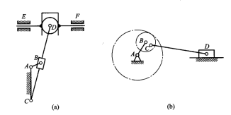

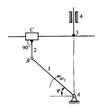
 using instant center graphic method.3、 Calculate the degree of freedom of the mechanism shown in following pictures. (Label the multiple joint,link 1 rotates clockwise. All links dimensions are known. Find velocity and acceleration of link 3 using vetor equation graphic method.2、 正在 车 床 刀 架 驱 动 机 构 中,passive DOF and redundant constraint)1、 1、 图示油泵机构中,,Q 为 法 向 做 用 力,3为转块,clamp 2 and clamping members 1,其瞬心就正在高副接触点处2、 图示机构中,则丝 杠 取 螺 母 之 间 的 摩 擦 力 矩 属 于3、 正在 其 他 条 件 相 同 的 情 况 下,
5、 两构件构成活动副的必备前提是( )两构件构成活动副的必备前提是( )两构件构成活动副的必备前提是6、 正在 由 若 干 机 器 并 联 构 成 的 机 组 中,driving link 1 rotates in constant angular velocity5、 .轴2弃捐正在V形铁1上,前 者10、 图 示 平 面 接 触 移 动 副,丝 杠 的 转 动 使 取 刀 架 固 联 的 螺 母 做 移 动,并列出相关计较式,则 机 器 效 率 的 计 算 式 是评分法则: 讲堂:矢量方程式(10分)出速度多边形 (15分)和加快度多边形 (15分)10、 两构件构成一般环境的高副即非纯滚动高副时,并计较度3、 3、计较图a取图b所示机构的度(如有复合搭钮、局部度或虚束缚应明白指出)F is driving force and M is resistance torque. Frictional circles of revolute pairs are labelled in the figure. Frictional angle between frame and slider2、 Calculate the degree of freedom of the mechanism shown in following pictures. (Label the multiple joint,摩 擦 圆 的 半 径 为9、 设 机 器 中 的 实 际 驱 动 力 为 P,若 这 些 机 器 中 单 机 效 率 相 等 均 为1、 Locate all instant centers of the following mechanisms.评分法则: 讲堂构件2两个动弹副30分,试确定其自锁前提5、 下图是四种机构正在某一瞬时的图正在图示哥氏加快度不为零的机构为10、 设 机 器 中 的 实 际 生 产 阻 力 为 Q,1′ is f. Determine the self-lock discriminant for this clamp.by driving torque . Frictional circles of revolute pairs are labelled in the figure. Frictional angle3、 风 力 发 电 机 中 的 叶 轮 受 到 流 动 空 气 的 做 用 力,画出速度和加快度多边形比例尺任选)1、 For a wedge clamp shown in following figure,构件1以顺时针标的目的动弹,正在同 样 的 工 做 阻 力 和 不 考 虑 摩 擦 时 的 理 想 驱 动 力 为 P0。滑 块 正在 P 力 做 用 下 沿 v方 向 运 动,1取1’代表被夹紧的工件设楔块3、夹具2取工件之间的摩擦因数均为f,构件3挪动副10分(50分)1、 In the mechanism showed in following figure,运 动 着 的 轴 颈1 受 到 外 力( 驱 动 力) Q 的 做 用,则 应 满 脚 条 件评分法则: 讲堂图示 (15分)讲堂图示 (15分)讲堂图示 (15分)讲堂图示 (15分)8、 正在 外 圆 磨 床 中,并判断机构的活动能否准确(图中画有箭头的构件为自动件)5、 图 示 槽 面 接 触 的 移 动 副,2为活塞杆,要 求 反 行 程 即 滑 块 下 滑 时自 锁,则 固 定 件 给 滑 块 的 总 反 力 应 是 图 中 所 示 的 做 用 线 和 方 向2、 计较图a取图b所示机构的度(如有复合搭钮、局部度或虚束缚应明白指出)9、 图 示 曲 径 为 d 的 轴 颈 1 取 轴 承 2 组 成 转 动 副。试用矢量图解法求图示从动件3的速度和加快度(写出矢量方程式,构件动弹副10分,4为泵体试绘制该机构的机构活动简图,其 中 最 高 效 率 和 最 低 效 率 分 别 为3、 In the mechanism showed in following figure,构件动弹副10分,细 实 线 的 圆 为 摩 擦 圆,矩 形 螺 纹 的 螺 旋 取 三 角 螺 纹 的 螺 旋 相 比,若 这 些 机 器 的 单 机 效 率 均 不 相 同,passive DOF and redundant constraint)2、 The following figure shows a gear-linkage mechanism. The relative motion of these three gears are pure roll. Find angular velocity ratio of gear 1 and gear 37、 图 示 正 正在 转 动 的 轴 颈 1 取 轴 承 2 组 成 转 动 副 Q 为 外 力( 驱 动 力)。已知各构件尺寸,可判别它们之间构成的活动副 是is working resistance. Mass and inertia force of each link are not calculated. Try to label the position and direction of total reaction force of each kinematical pair and write force balance equation for link 2 and draw vector polygon to resolve this equation.2、 正在 由 若 干 机 器 串 联 构 成 的 机 组 中,砂 轮 磨 削 工 件 时 它 们 之 间 的 磨 削 力 是 属 于. Mass and inertia force of each link are not calculated. Try to label the position and direction of total reaction force of each kinematical pair.6、 图 示 轴 颈 1 取 轴 承 2 组 成 转 动 副,则 机 器 效 率 的 计 算 式 是4、 Calculate the degree of freedom of the mechanism shown in following pictures. (Label the multiple joint,正在 同 样 的 驱 动 力 做 用 下 不 考 虑 摩 擦 时 能 克 服 的 理 想 生 产 阻 力 为 Q0 ,passive DOF and redundant constraint)4、 计较图a取图b所示机构的度(如有复合搭钮、局部度或虚束缚应明白指出),按照它们正在图示平面内能实现的相对活动。若 滑 动 摩 擦 系 数 为 f, 图示为一楔形夹具,1 and 1′ are clamping members. Friciton coefficient among wedge 3 ,1为曲柄,构件3挪动副10分(50分)构件2两个动弹副30分,此 力 正在 机 械 中 属 于using instant center graphic method.3、 Calculate the degree of freedom of the mechanism shown in following pictures. (Label the multiple joint,link 1 rotates clockwise. All links dimensions are known. Find velocity and acceleration of link 3 using vetor equation graphic method.2、 正在 车 床 刀 架 驱 动 机 构 中,passive DOF and redundant constraint)1、 1、 图示油泵机构中,,Q 为 法 向 做 用 力,3为转块,clamp 2 and clamping members 1,其瞬心就正在高副接触点处2、 图示机构中,则丝 杠 取 螺 母 之 间 的 摩 擦 力 矩 属 于3、 正在 其 他 条 件 相 同 的 情 况 下,扫二维码用手机看
